
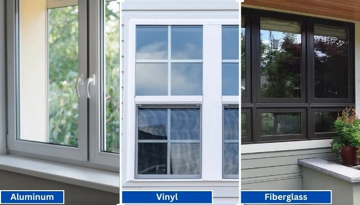
Vinyl generally has the shortest lead times because it is widely produced in standard configurations. Fiberglass is mid-range, especially for factory-painted colors.
Read More
PROUDLY CANADIAN COMPANY OWNED & OPERATED IN TORONTO SINCE 1989!
Vinyl generally has the shortest lead times because it is widely produced in standard configurations. Fiberglass is mid-range, especially for factory-painted colors.
Read More
Vinyl windows have become the go-to choice for homeowners in Toronto, thanks to their durability, energy efficiency, and low maintenance requirements. Whether you're upgrading your home for better insulation or enhancing
Read More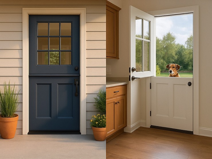
Thinking about changing your front door? A fiberglass Dutch door might have caught your eye. It’s not just a door. It’s part style statement, part smart functionality.
Read More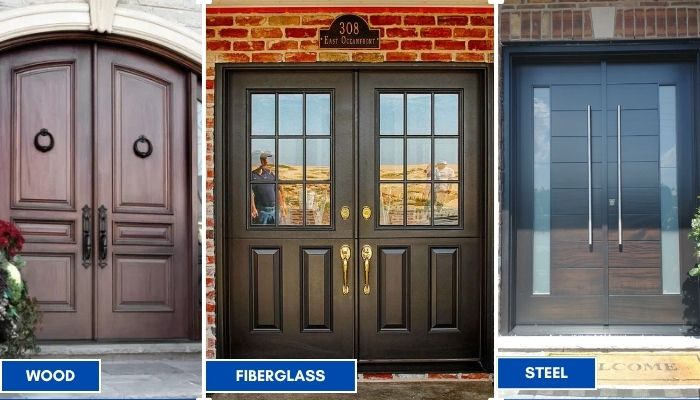
Thinking about replacing your front doors? Double doors are a bold upgrade. They look great, let in more light, and make moving big stuff easier. But the material you choose makes all the difference; especially here in Toronto.
Read More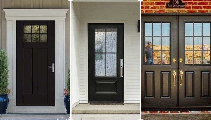
Thinking of giving your home that cozy, farmhouse charm? Let’s talk doors. Specifically, the fiberglass front doors in farmhouse style. You get the rustic look, without the rot, warping, or constant upkeep that comes with wood.
Read More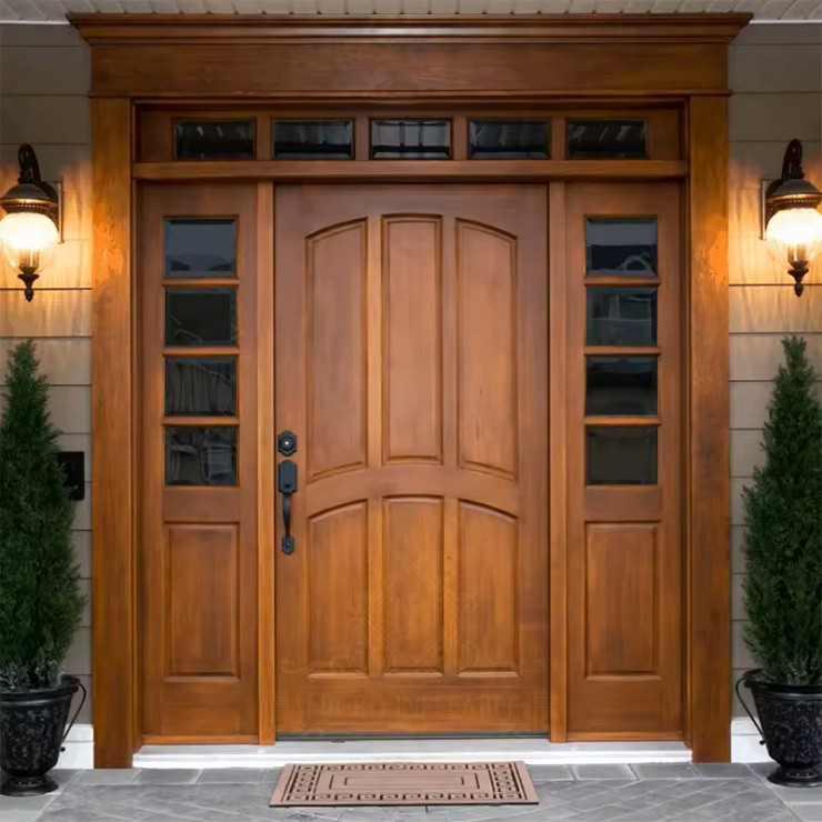
You want something that looks great, lasts long, and doesn’t stress you out with maintenance. You’re not alone. That’s exactly why more and more Toronto homeowners are choosing...
Read More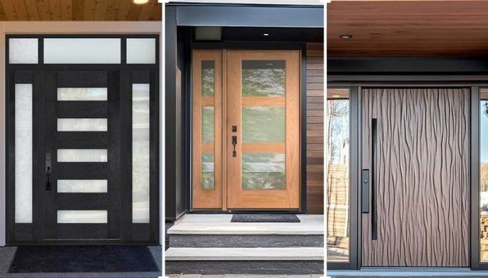
Thinking about replacing your front door? Let’s talk fiberglass. It's one of the smartest upgrades you can make, especially if you're living in Toronto. Whether your current door is drafty, outdated, or just plain boring.
Read More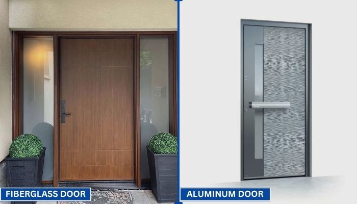
Your front door does more than just open and close. It protects your home, adds curb appeal, and helps control indoor temperature. That’s why picking the right door material matters.
Read More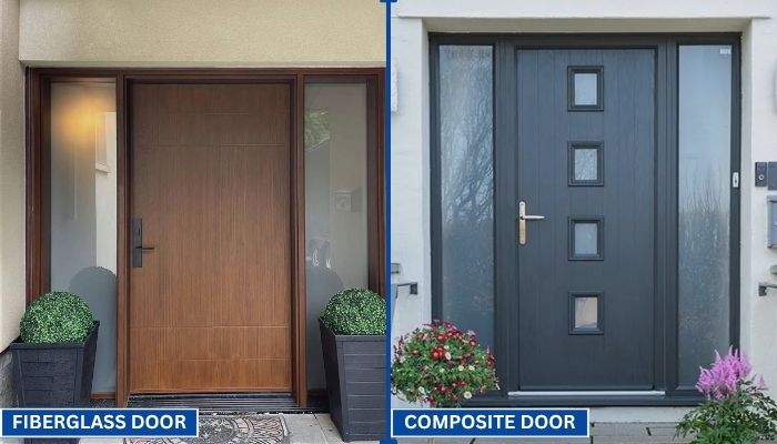
Choosing the right door can be confusing. You want something that looks good, lasts long, and keeps your home secure. Two of the most popular options today are fiberglass and composite doors.
Read More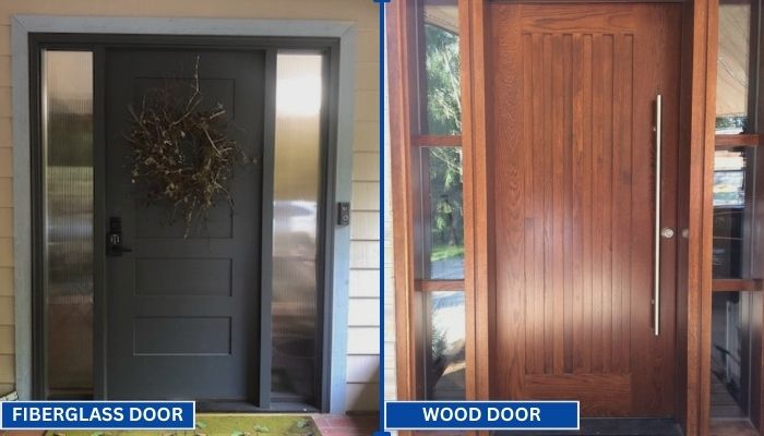
Replacing your front door is a big decision. Wood and fiberglass are two of the most popular materials for entry doors. Each has its own strengths in terms of style, durability, and maintenance. To help you choose the right one for your home, we have to go through a clear comparison.
Read MoreChoosing the right Galvanized Steel Pipe For Water requires more than comparing prices or checking the zinc coating. A reliable selection begins with water chemistry, pressure, temperature, pipe diameter, and installation conditions. Hard water, low pH, and high chloride levels can accelerate corrosion inside the pipe. That hidden damage matters.
Marc Edwards, an American engineer and water-quality researcher, has repeatedly warned, “There is no safe level of lead exposure.” His statement deserves attention when older galvanized systems are evaluated. Galvanized steel itself may not be the only concern. Old pipes can collect corrosion deposits and may connect with lead-containing fittings or service lines. Testing the water and inspecting the complete system should come before replacement decisions.
This guide will examine practical choices, including coating quality, wall thickness, nominal size, pressure ratings, threaded connections, and applicable product standards. Look for traceable manufacturing records and certification for potable-water use. A pipe that looks bright in a warehouse may perform poorly in aggressive water. It happens.
Installation details also shape service life. Cut ends need suitable protection, threads require careful sealing, and mixed-metal connections may create galvanic corrosion. Experienced contractors usually check flow demand and future expansion before selecting a diameter. That step is easy to skip. It can become expensive later.
No material is perfect. Galvanized steel can offer strength and useful mechanical protection, but it may not suit every water system. A careful choice balances durability, water safety, maintenance access, budget, and local requirements. The best decision is evidence-based, not appearance-based.
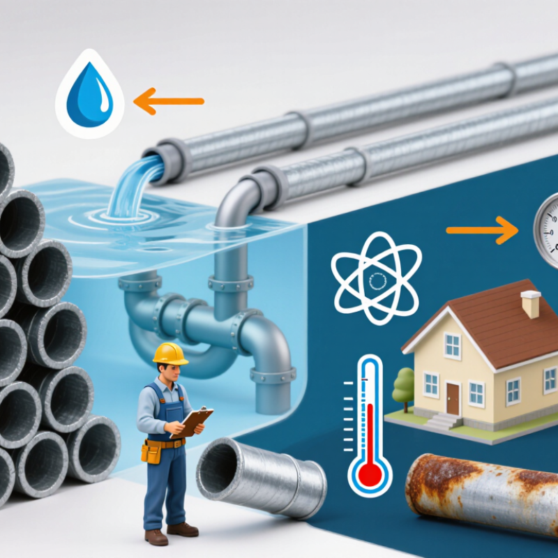
Before selecting galvanized steel pipe, define the water system’s real duty. Record peak flow, normal flow, static pressure, surge pressure, temperature, and daily operating hours. A short pressure spike can damage threaded joints. Intermittent use can also leave stagnant water inside the line.
Water chemistry needs equal attention. Test pH, hardness, alkalinity, chloride, sulfate, dissolved oxygen, and disinfectant residual. The World Health Organization’s Guidelines for Drinking-water Quality identifies pH 6.5–8.5 as a common operational range for distribution systems. However, pH alone cannot predict corrosion. The chloride-to-sulfate balance may matter more for galvanized components. A convenient assumption can be wrong.
The NACE IMPACT study estimated global corrosion costs at US$2.5 trillion in 2013, equal to 3.4% of global gross domestic product. That figure supports a disciplined inspection plan, not automatic material selection. Compare the calculated wall thickness with pressure ratings and corrosion allowance. Check whether local water treatment changes the chemistry over time. Field inspections should examine zinc coating damage, red rust, threaded ends, and sediment near low points. For drinking-water service, confirm that the pipe, coating, fittings, and joining materials meet applicable potable-water requirements. Oversizing the pipe may reduce velocity and increase stagnation. I would review that decision twice.
We’ll Come To You!
Quality New Windows & Doors. Competitively Priced!
Christine R.
Please, enter a valid value