
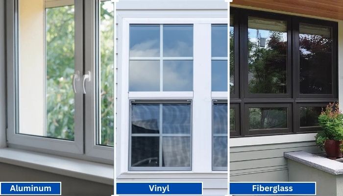
Vinyl generally has the shortest lead times because it is widely produced in standard configurations. Fiberglass is mid-range, especially for factory-painted colors.
Read More
PROUDLY CANADIAN COMPANY OWNED & OPERATED IN TORONTO SINCE 1989!
Vinyl generally has the shortest lead times because it is widely produced in standard configurations. Fiberglass is mid-range, especially for factory-painted colors.
Read More
Vinyl windows have become the go-to choice for homeowners in Toronto, thanks to their durability, energy efficiency, and low maintenance requirements. Whether you're upgrading your home for better insulation or enhancing
Read More
Thinking about changing your front door? A fiberglass Dutch door might have caught your eye. It’s not just a door. It’s part style statement, part smart functionality.
Read More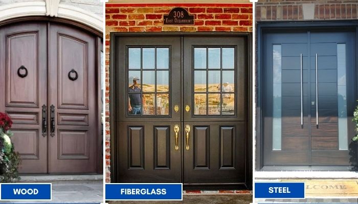
Thinking about replacing your front doors? Double doors are a bold upgrade. They look great, let in more light, and make moving big stuff easier. But the material you choose makes all the difference; especially here in Toronto.
Read More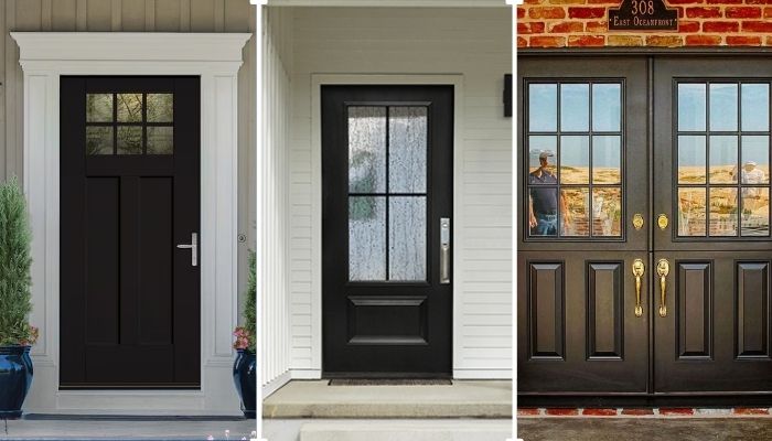
Thinking of giving your home that cozy, farmhouse charm? Let’s talk doors. Specifically, the fiberglass front doors in farmhouse style. You get the rustic look, without the rot, warping, or constant upkeep that comes with wood.
Read More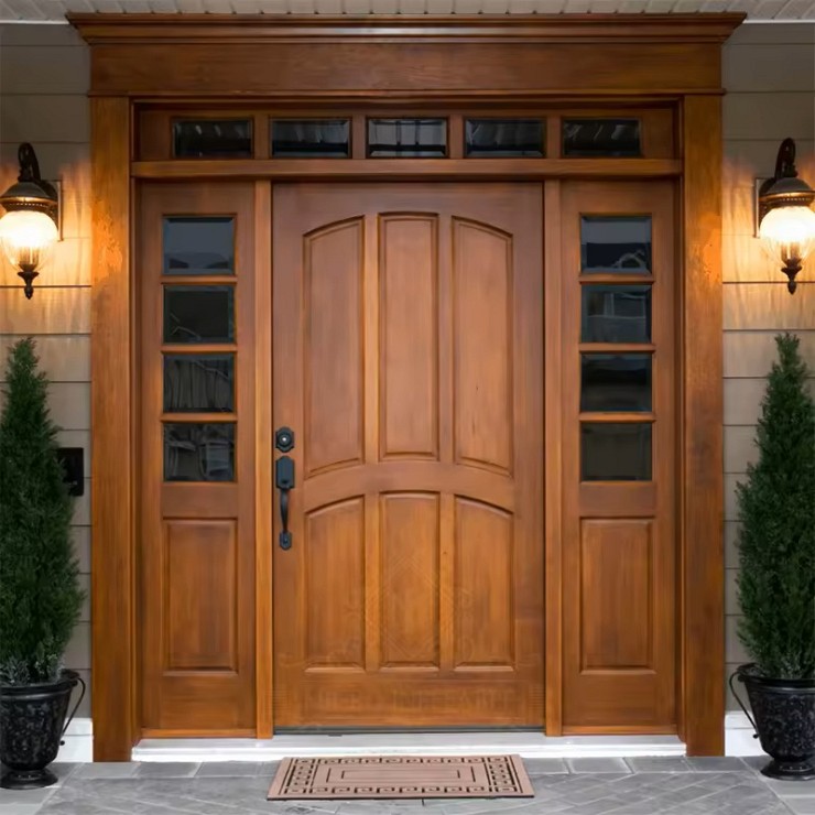
You want something that looks great, lasts long, and doesn’t stress you out with maintenance. You’re not alone. That’s exactly why more and more Toronto homeowners are choosing...
Read More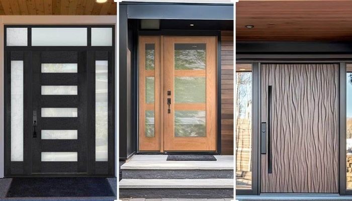
Thinking about replacing your front door? Let’s talk fiberglass. It's one of the smartest upgrades you can make, especially if you're living in Toronto. Whether your current door is drafty, outdated, or just plain boring.
Read More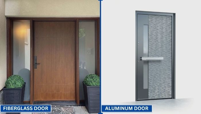
Your front door does more than just open and close. It protects your home, adds curb appeal, and helps control indoor temperature. That’s why picking the right door material matters.
Read More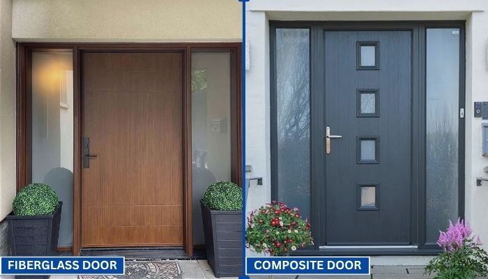
Choosing the right door can be confusing. You want something that looks good, lasts long, and keeps your home secure. Two of the most popular options today are fiberglass and composite doors.
Read More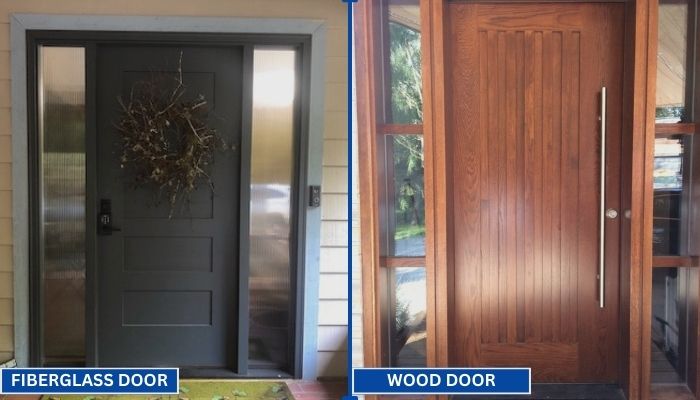
Replacing your front door is a big decision. Wood and fiberglass are two of the most popular materials for entry doors. Each has its own strengths in terms of style, durability, and maintenance. To help you choose the right one for your home, we have to go through a clear comparison.
Read MoreChoosing an eccentric butterfly valve in 2026 requires more than comparing catalog prices. The correct choice begins with the medium, pressure, temperature, flow direction, and operating frequency. A valve handling abrasive slurry faces different risks than one controlling clean water. Small details matter. Seat wear, shaft alignment, and disc clearance can determine service life.
Valve engineer and author R. W. Zappe wrote, “The selection of a valve depends on the service conditions.” This principle remains practical today. An eccentric butterfly valve reduces seat rubbing during operation, which can support smoother movement and lower wear. However, the design is not automatically suitable for every pipeline. A poorly matched seal material may fail under heat, chemicals, or repeated cycling. That point is easy to overlook.
This guide examines the decisions engineers make before approving a purchase. It considers valve size, pressure class, body materials, seat construction, actuator torque, and maintenance access. It also reviews installation space, shutoff expectations, and compatibility with modern control systems. Reliable selection should include manufacturer test data, recognized standards, traceable materials, and field experience. Ask difficult questions. What happens during a power loss? Can technicians replace the seat without removing the valve? Will the actuator provide enough closing torque after years of deposits?
No checklist is flawless. Actual operating conditions often differ from drawings. Therefore, this 2026 guide combines technical evaluation with practical judgment, helping engineers choose an eccentric butterfly valve that performs consistently rather than merely appearing economical.
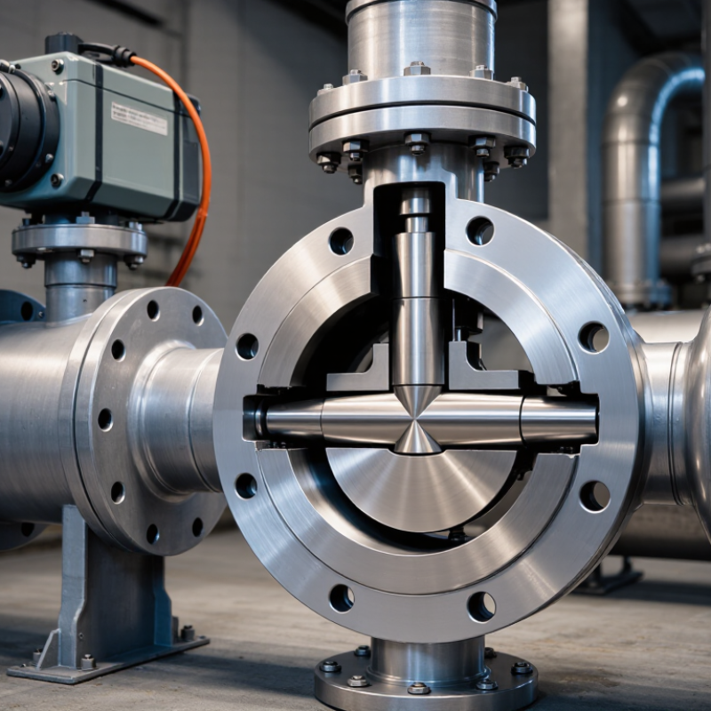
2026 How to Choose an Eccentric Butterfly Valve?
Understanding Eccentric Butterfly Valve Design and Operating Principles
An eccentric butterfly valve moves its shaft away from the disc centerline. That offset changes the sealing path. During opening, the disc lifts away from the seat instead of scraping across it. This reduces friction, wear, and actuator demand. Single-offset designs suit moderate service, while double-offset designs improve disc release. Triple-offset geometry adds a conical, right-angle sealing action for demanding thermal service. The distinction matters.
Operating conditions should guide the selection. Check pressure, temperature, media composition, flow velocity, and required leakage class. API 609 covers butterfly valve design categories, while ISO 5211 helps match the valve to its actuator. ISO 5208 provides leakage-testing classifications. The International Energy Agency reported that industry represented about 37% of global final energy consumption in 2022. Lower operating torque can support efficiency, but it never replaces correct sizing.
Market scale also deserves attention. Grand View Research estimated the global industrial valves market at approximately USD 79 billion in 2023. That number signals widespread use, not automatic reliability. A practical review should examine shaft bearings, seat materials, flange alignment, and available maintenance space. A neat datasheet can still mislead. I would question unusually low torque figures, especially with abrasive slurry or cold-start conditions. Field conditions are rarely perfect. Temperature cycling, pipe stress, and installation errors can quietly shorten service life.
| Selection Dimension | Design or Operating Principle | Typical Options | Why It Matters | Recommended Selection Guidance |
|---|---|---|---|---|
| Valve Offset Configuration | The shaft position is moved away from the centerline so the disc separates from the seat progressively during opening. | Single offset, double offset, or triple offset. | Offset geometry reduces rubbing, operating torque, and seat wear compared with a centered butterfly valve. | Use double offset for demanding general service; consider triple offset when high temperature, high pressure, or bubble-tight metal seating is required. |
| Single-Offset Design | The shaft is offset from the pipe centerline, allowing the disc to move away from the seat as the valve begins to open. | Usually resilient-seated construction. | Provides lower friction and better seat life than a concentric design while retaining a relatively simple construction. | Select where moderate pressure and temperature conditions are present and a resilient shutoff seat is suitable. |
| Double-Offset Design | The shaft is offset from both the pipe centerline and the disc or seat centerline. The disc lifts away from the seat more quickly during opening. | High-performance butterfly valve with resilient or laminated seat. | Reduces sliding contact, lowers breakaway torque, and improves durability for frequent operation. | A practical choice for water, HVAC, general process, utility, and many industrial isolation applications. |
| Triple-Offset Design | Two shaft offsets are combined with a conical seat geometry. The sealing surfaces are designed to separate without rubbing through most of the stroke. | Metal-seated, torque-seated construction. | Supports high-temperature service, fire-safe designs, and robust shutoff where soft seats may be unsuitable. | Choose when temperature, fire safety, emissions control, or severe service requirements exceed the capability of a resilient seat. |
| Valve Function | Butterfly valves regulate or isolate flow by rotating the disc approximately 90 degrees around the shaft. | On/off isolation or throttling control. | A valve intended for control service must tolerate continuous intermediate positioning and the resulting fluid forces. | Use an appropriate control characteristic, actuator, and anti-cavitation assessment when the valve will throttle continuously. |
| Nominal Size | Butterfly valves are compact because the disc rotates within the pipe rather than moving linearly outside the flow path. | Commonly available from small utility sizes to very large pipeline sizes; actual availability depends on the applicable standard and design. | Correct sizing affects pressure loss, actuator torque, installation space, and total cost. | Select the size from required flow, allowable pressure drop, line velocity, and connection standard—not from pipe size alone. |
| Pressure Class | The pressure rating defines the allowable pressure-temperature envelope of the complete valve assembly. | Examples include ASME Class 150, Class 300, and Class 600, or PN-rated systems such as PN10, PN16, PN25, and PN40. | The rated pressure can decrease as operating temperature increases, depending on materials and the governing standard. | Match the valve rating to the flange rating and verify pressure-temperature derating from the manufacturer’s certified data. |
| Temperature Range | Seat and body materials determine resistance to temperature, thermal cycling, and process compatibility. | Resilient seats for moderate temperatures; graphite, laminated metal, or metal seats for higher-temperature service. | Excessive temperature can cause seat degradation, leakage, shaft expansion, or loss of actuator margin. | Specify minimum and maximum operating temperature, start-up temperature, shut-down temperature, and thermal cycling frequency. |
| Seat Material | The seat forms the sealing interface between the disc and the valve body or seat ring. | EPDM, NBR, PTFE-based materials, graphite, laminated metal, or solid metal, depending on service. | Seat material determines chemical resistance, temperature capability, leakage performance, and expected service life. | Check compatibility with the fluid, concentration, temperature, pressure, abrasion level, and cleaning chemicals. |
| Body and Disc Materials | The pressure boundary and wetted components must withstand mechanical loads, corrosion, erosion, and process temperature. | Carbon steel, ductile iron, stainless steel, nickel-based alloys, and corrosion-resistant overlays are common options. | Material selection affects corrosion allowance, weight, pressure capability, and lifecycle cost. | Base the selection on the complete fluid composition, including chlorides, solids, oxygen, moisture, and upset conditions. |
| End Connection | The valve must connect correctly to the pipeline while maintaining alignment and gasket compression. | Wafer, lug, double-flanged, butt-weld, and other standardized configurations. | Connection type influences installation, removal, dead-end service, bolt loading, and maintenance access. | Confirm flange dimensions, facing, bolt pattern, pressure class, available clearance, and whether dead-end pressure is permitted. |
| Flow Coefficient and Pressure Drop | The rotating disc creates a variable restriction. Flow capacity changes with valve angle and disc geometry. | Manufacturer-published Cv or Kv data for the selected size and trim. | An undersized valve may create excessive pressure loss; an oversized valve may provide poor control resolution. | Verify flow rate, fluid density, viscosity, vapor pressure, line velocity, and allowable pressure drop at each operating case. |
| Leakage Requirement | Shutoff performance depends on seat design, manufacturing tolerances, differential pressure, and actuator seating torque. | Soft-seat tight shutoff or metal-seat leakage class specified by the applicable test standard. | The required leakage level determines seat construction and may significantly affect temperature and pressure capability. | State the required leakage class and test direction; do not assume that every butterfly valve provides zero visible leakage. |
| Actuator Type | The actuator supplies the torque needed to unseat, rotate, and securely close the disc under the worst operating condition. | Manual lever or gearbox, pneumatic, electric, or hydraulic actuator. | Actuator selection affects response time, fail position, automation, safety, and operating cost. | Use certified torque data that includes seating, unseating, dynamic, packing, and safety margins across the full pressure and temperature range. |
| Fail-Safe Position | An automated valve can be designed to move to a defined position when control power or instrument air is lost. | Fail-open, fail-closed, or fail-in-place, depending on the actuator and application. | The correct failure position is part of the process safety strategy. | Determine the safe state through a documented hazard review and confirm actuator, solenoid, air supply, and emergency shutdown requirements. |
| Cavitation and Noise | Large pressure reduction across a partially open valve can cause cavitation in liquids or high noise and vibration in gases. | Standard disc, modified trim, staged pressure reduction, or an alternative valve type for severe control duty. | Cavitation can damage the disc, seat, body, and downstream piping. | Evaluate pressure ratio, vapor pressure, downstream pressure, flow velocity, noise limits, and operating position before final selection. |
| Solids and Abrasion | Suspended particles can erode sealing surfaces and become trapped around the disc or seat. | Hardened trim, abrasion-resistant coatings, slurry-rated designs, or alternative valve geometries. | Abrasion may increase leakage, torque, and maintenance frequency. | Specify particle size, concentration, hardness, settling tendency, and whether the valve will operate frequently in a partially open position. |
| Installation Orientation | Disc clearance, shaft orientation, support, and access must be considered during installation. | Horizontal or vertical piping installation, subject to the valve and actuator instructions. | Improper alignment or insufficient clearance can cause disc interference, flange damage, or actuator overload. | Check pipe alignment, flange spacing, disc sweep, actuator clearance, support requirements, and flow-direction markings. |
| Applicable Standards | Standards define dimensions, pressure ratings, materials, testing, face-to-face length, and performance requirements. | Examples include ISO 5752, EN 593, API 609, ASME B16.34, and applicable leakage-test standards. | Using the correct standard prevents dimensional mismatch and unclear acceptance criteria. | Specify the required design, inspection, testing, flange, fire-safe, emissions, and certification standards in the purchase document. |
| Maintenance and Lifecycle Cost | Eccentric geometry can reduce seat friction and wear, but maintenance still depends on service severity and operating frequency. | Replaceable seat, replaceable seal components, accessible packing, and condition-monitoring provisions. | Purchase price alone does not represent the total cost of ownership. | Compare inspection intervals, spare parts, actuator maintenance, downtime, energy loss, corrosion allowance, and expected cycle life. |
| Final Selection Checklist | A complete specification connects process conditions, mechanical design, sealing requirements, actuation, and installation constraints. | Size, pressure, temperature, fluid, materials, seat, leakage, end connection, actuator, standards, and testing. | Missing process information can result in incorrect torque, premature seat failure, excessive pressure loss, or unsafe operation. | Obtain certified dimensional, pressure-temperature, torque, Cv/Kv, material, leakage, and test documentation before approval. |
We’ll Come To You!
Quality New Windows & Doors. Competitively Priced!
Christine R.
Please, enter a valid value