
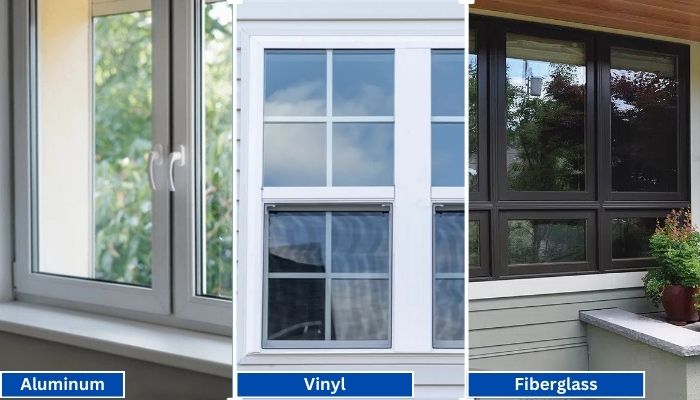
Vinyl generally has the shortest lead times because it is widely produced in standard configurations. Fiberglass is mid-range, especially for factory-painted colors.
Read More
PROUDLY CANADIAN COMPANY OWNED & OPERATED IN TORONTO SINCE 1989!
Vinyl generally has the shortest lead times because it is widely produced in standard configurations. Fiberglass is mid-range, especially for factory-painted colors.
Read More
Vinyl windows have become the go-to choice for homeowners in Toronto, thanks to their durability, energy efficiency, and low maintenance requirements. Whether you're upgrading your home for better insulation or enhancing
Read More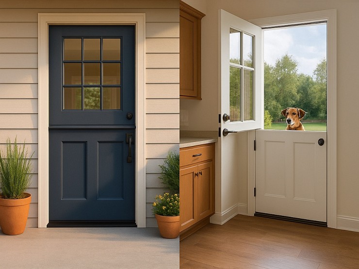
Thinking about changing your front door? A fiberglass Dutch door might have caught your eye. It’s not just a door. It’s part style statement, part smart functionality.
Read More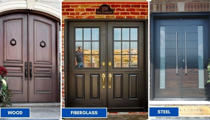
Thinking about replacing your front doors? Double doors are a bold upgrade. They look great, let in more light, and make moving big stuff easier. But the material you choose makes all the difference; especially here in Toronto.
Read More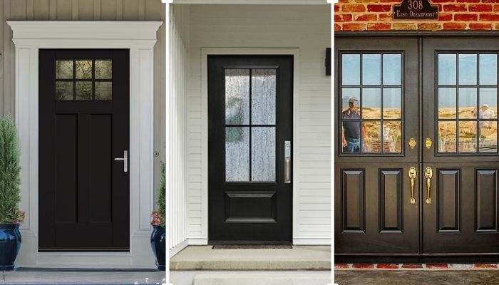
Thinking of giving your home that cozy, farmhouse charm? Let’s talk doors. Specifically, the fiberglass front doors in farmhouse style. You get the rustic look, without the rot, warping, or constant upkeep that comes with wood.
Read More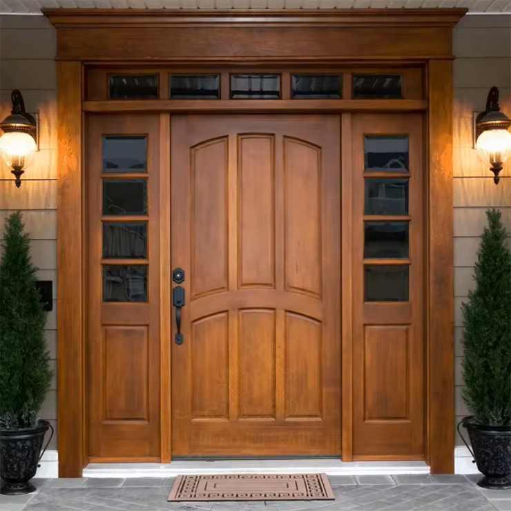
You want something that looks great, lasts long, and doesn’t stress you out with maintenance. You’re not alone. That’s exactly why more and more Toronto homeowners are choosing...
Read More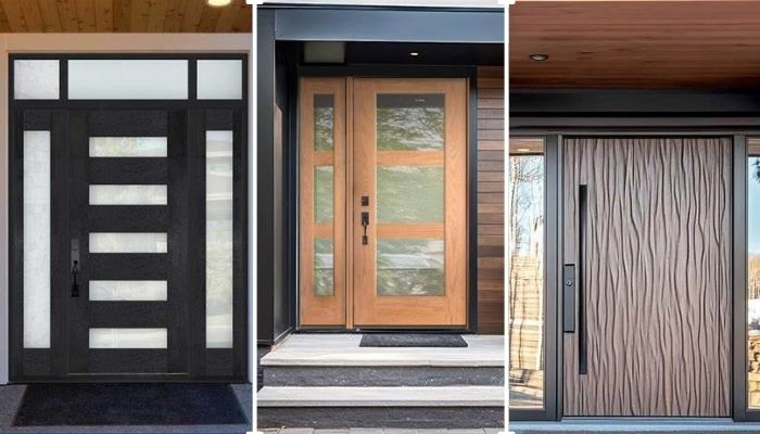
Thinking about replacing your front door? Let’s talk fiberglass. It's one of the smartest upgrades you can make, especially if you're living in Toronto. Whether your current door is drafty, outdated, or just plain boring.
Read More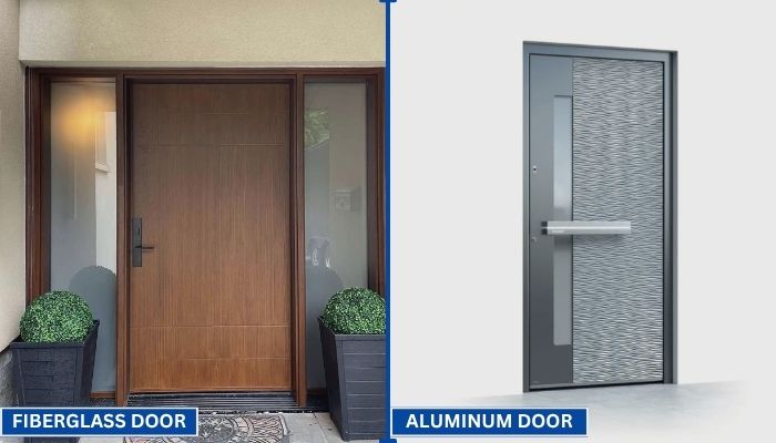
Your front door does more than just open and close. It protects your home, adds curb appeal, and helps control indoor temperature. That’s why picking the right door material matters.
Read More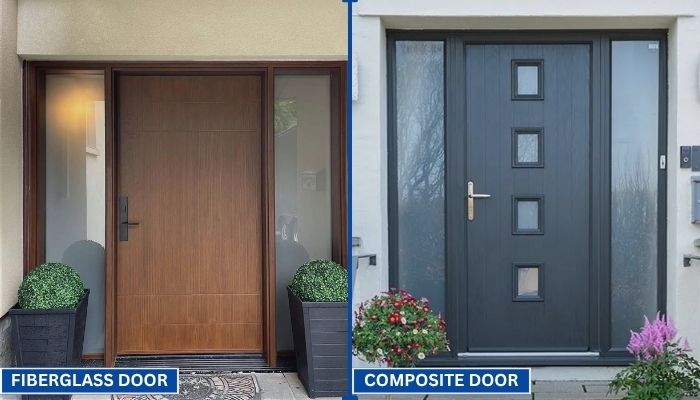
Choosing the right door can be confusing. You want something that looks good, lasts long, and keeps your home secure. Two of the most popular options today are fiberglass and composite doors.
Read More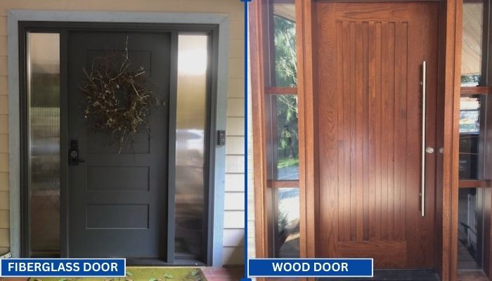
Replacing your front door is a big decision. Wood and fiberglass are two of the most popular materials for entry doors. Each has its own strengths in terms of style, durability, and maintenance. To help you choose the right one for your home, we have to go through a clear comparison.
Read MoreChoosing the right Light Pole manufacturer can shape a project’s safety, appearance, and long-term operating cost. Global buyers often compare suppliers across regions, materials, certifications, production capacity, and delivery performance. A reliable manufacturer should explain its process clearly, from steel inspection and welding to galvanizing, coating, and final load testing.
Field experience matters here. A pole may look excellent in a catalog, yet perform poorly when exposed to coastal salt, strong winds, or repeated temperature changes. Buyers should review verified project references, technical drawings, wind-load calculations, and quality-control records. Ask for details.
This guide examines leading Light Pole manufacturers serving international markets. It considers practical factors, including tapered steel poles, aluminum options, high-mast systems, solar lighting poles, and custom foundation requirements. It also reviews communication, packaging, lead times, after-sales support, and the manufacturer’s ability to meet local specifications.
Not every supplier excels everywhere. Some offer competitive pricing but limited engineering support. Others provide advanced manufacturing but require larger minimum orders. That difference matters. Product claims should be checked against test reports, independent certifications, and completed installations whenever possible.
The goal is not to promote the biggest name. It is to identify dependable partners for different project conditions. A careful comparison can reduce redesigns, shipping damage, installation delays, and unexpected maintenance. Still, this list is not absolute. Buyer requirements change, and supplier performance should be reassessed before every major purchase.

A top light pole manufacturer understands that global buyers need more than a polished catalog. They need poles that perform in real streets, ports, parks, and industrial sites. Experienced manufacturers verify steel grades, wall thickness, weld quality, and protective coatings through documented inspections. They also consider wind speed, pole height, luminaire weight, foundation design, and local soil conditions. A beautiful pole can still fail when these details are ignored.
Reliable production depends on repeatable engineering and transparent testing. Strong suppliers provide structural calculations, material certificates, dimensional reports, and clear installation instructions. They use suitable galvanizing or coating systems for humid, coastal, and polluted environments. Independent testing can strengthen confidence, especially for large infrastructure projects. However, compliance documents should match the actual shipment, not a previous production batch. This small detail is often overlooked.
Global service also defines quality. A capable manufacturer communicates clearly across time zones, protects components during shipping, and supports replacement parts years after delivery. Custom flange plates, access doors, cable openings, and color finishes may be necessary for different projects. Yet customization should not replace basic engineering discipline. No supplier gets every decision right. Buyers should ask how failures are handled, not only how success is advertised. Honest technical discussions usually reveal more than impressive promises.
We’ll Come To You!
Quality New Windows & Doors. Competitively Priced!
Christine R.
Please, enter a valid value